http://ng-ccie.blogspot.com/2020/02/bgp-communities-ospf-domain-id-and-ospf.html
My intention now is to go deeper into these BGP communities and show how we can work with them.
When OSPF is being used as the PE-CE protocol, the PEs needs to inform other PEs how to interpret the routes they are announcing through MP-BGP, so this way they can choose what type of LSA to use when redistributing from MP-BGP back into OSPF. The communities used for that purpose are OSPF Domain-ID and OSPF RT, and they are attached to the prefixes by the original PE when redistributing from OSPF into MP-BGP. Then, the destination PE gets to know which LSA type to use in the redistribution from MP-BGP back into OSPF.
Let’s study the next scenario:

Assume both PEs use the same OSPF process-id, and that there is not domain-id configured. In our case, both PEs will have the same domain-id as this is extracted from the process-id.
In the next output, we see both PEs running OSPF 100 with their respective CEs:
PE1#show ip ospf 100
 Routing Process "ospf 100" with ID 10.10.11.2
   Domain ID type 0x0005, value 0.0.0.100
PE2#show ip ospf 100
 Routing Process "ospf 100" with ID 10.10.22.1
   Domain ID type 0x0005, value 0.0.0.100
As we can see, both PEs have the same domain-id 0.0.0.100.
Let’s check how PE1 receives in BGP the loopback of CE2 that was previously redistributed:
PE1#show bgp vpnv4 unicast all 2.2.2.2/32
BGP routing table entry for 1:1:2.2.2.2/32, version 116
Paths: (1 available, best #1, table VPN_A)
  Not advertised to any peer
  Local
    100.100.100.2 (metric 11) from 100.100.100.2 (100.100.100.2)
      Origin incomplete, metric 11, localpref 100, valid, internal, best
      Extended Community: RT:1:1 OSPF DOMAIN ID:0x0005:0x000000640200
        OSPF RT:0.0.0.1:2:0 OSPF ROUTER ID:10.10.22.1:0
      mpls labels in/out nolabel/21
The OSPF Domain-ID for this prefix is 0x00000064 (0.0.0.100 in decimal).
Since there are no sham-links configured and both PEs have the same Domain-ID, the prefix will be redistributed as an INTER-AREA prefix (LSA-3).
Let’s check on CE1 if this is true:
CE1#show ip route 2.2.2.2
Routing entry for 2.2.2.2/32
  Known via "ospf 100", distance 110, metric 21, type inter area
  Last update from 10.10.11.2 on FastEthernet0/0, 00:00:00 ago
  Routing Descriptor Blocks:
  * 10.10.11.2, from 10.10.11.2, 00:00:00 ago, via FastEthernet0/0
      Route metric is 21, traffic share count is 1
What will happen if we change the domain-id in PE2?
By specifying the domain-id in the configuration, the OSPF process ID is no longer taken into account when building the domain-id, only the value specified is used.
PE2(config)#router ospf 100 vrf VPN_A
PE2(config-router)#domain-id 100.100.100.2
PE2(config-router)#end
PE1#shw bgp vpnv4 unicast all 2.2.2.2/32
BGP routing table entry for 1:1:2.2.2.2/32, version 126
Paths: (1 available, best #1, table VPN_A)
Flag: 0x820
  Not advertised to any peer
  Local
    100.100.100.2 (metric 11) from 100.100.100.2 (100.100.100.2)
      Origin incomplete, metric 11, localpref 100, valid, internal, best
      Extended Community: RT:1:1 OSPF DOMAIN ID:0x0005:0x646464020200
        OSPF RT:0.0.0.1:2:0 OSPF ROUTER ID:10.10.22.1:0
      mpls labels in/out nolabel/18
CE1#show ip route 2.2.2.2
Routing entry for 2.2.2.2/32
  Known via "ospf 100", distance 110, metric 11
  Tag Complete, Path Length == 1, AS 65000, , type extern 2, forward metric 10
  Last update from 10.10.11.2 on FastEthernet0/0, 00:00:12 ago
  Routing Descriptor Blocks:
  * 10.10.11.2, from 10.10.11.2, 00:00:12 ago, via FastEthernet0/0
      Route metric is 11, traffic share count is 1
      Route tag 3489725928
Now CE1 sees the prefix as an External prefix (LSA-5). And why is that? Well, by specifying two different domain-id’s in OSPF, the routing process assumes there are two different OSPF instances running inside the VPN. So it’s like if we were redistributing prefixes from one OSPF process to the other. And it’s seen as a LSA-5 Type 2 because that’s the redistributing type by default (if we wanted to change that, we should change the redistribute command under OSPF by specifying into which type of External LSA redistribute: Type 1 or Type 2).
Ok, nice!! But let’s try to play now with the BGP community OSPF RT. Until now, this community hasn’t given any info. But if we configure a sham-link between both PEs (check this post about how to create a sham-link), the values of the community OSPF RT will come into play.
Let’s check how PE1 sees CE2’s Loopback after configuring the sham-link
PE1#show bgp vpnv4 unicast all 2.2.2.2/32
BGP routing table entry for 1:1:2.2.2.2/32, version 138
Paths: (1 available, best #1, table VPN_A, RIB-failure(17))
  Not advertised to any peer
  Local
    100.100.100.2 (metric 11) from 100.100.100.2 (100.100.100.2)
      Origin incomplete, metric 11, localpref 100, valid, internal, best
      Extended Community: RT:1:1 OSPF DOMAIN ID:0x0005:0x646464020200
        OSPF RT:0.0.0.1:2:0 OSPF ROUTER ID:10.10.22.1:0
      mpls labels in/out nolabel/18
The value of Domain-ID is not taken into account any more because both PEs have a direct adjacency through the sham-link (the routers don’t interpret that there are two different OSPF instances running any more). As we can see, the community OSPF RT has the value 0.0.0.1:2:0.
The first 4 bytes (0.0.0.1) are for the area. In our case, all routers are in Area 1.
The 2 last bytes (:2:0) show which type of LSA must be used when redistributing this prefix into OSPF. The values 1 and 2 mean the LSA to use must be LSA-1 (Intra-Area LSA)
Let’s check on CE1 if the prefix is seen as Intra-Area:
CE1#show ip route 2.2.2.2
Routing entry for 2.2.2.2/32
  Known via "ospf 100", distance 110, metric 22, type intra area
  Last update from 10.10.11.2 on FastEthernet0/0, 00:07:24 ago
  Routing Descriptor Blocks:
  * 10.10.11.2, from 2.2.2.2, 00:07:24 ago, via FastEthernet0/0
      Route metric is 22, traffic share count is 1
Great!! It seems to be right!
Let’s see what happens if CE2 redistributes the prefix 22.22.22.22/32 into OSPF
PE1#sh bgp vpn uni all 22.22.22.22/32
BGP routing table entry for 1:1:22.22.22.22/32, version 32
Paths: (1 available, best #1, table VPN_A, RIB-failure(17))
Flag: 0x820
  Not advertised to any peer
  Local
    100.100.100.2 (metric 11) from 100.100.100.2 (100.100.100.2)
      Origin incomplete, metric 20, localpref 100, valid, internal, best
      Extended Community: RT:1:1 OSPF DOMAIN ID:0x0005:0x646464020200
        OSPF RT:0.0.0.0:5:1 OSPF ROUTER ID:10.10.22.1:0
      mpls labels in/out nolabel/20
Now the value of the community OSPF RT is 0.0.0.0:5:1. The value of 0.0.0.0 stands for no area (as we already know, external routes are not related to any area). And the value of :5:1 stands for LSA-5 Type 2. Let’s check if CE1 sees this prefix as external type 2 route
CE1#sh ip route 22.22.22.22
Routing entry for 22.22.22.22/32
  Known via "ospf 100", distance 110, metric 20, type extern 2, forward metric 21
  Last update from 10.10.11.2 on FastEthernet0/0, 00:07:28 ago
  Routing Descriptor Blocks:
  * 10.10.11.2, from 2.2.2.2, 00:07:28 ago, via FastEthernet0/0
      Route metric is 20, traffic share count is 1
Ok, it seems to be true!!
So, as we can see, the BGP community OSPF RT tells the PE router which type of LSA to use when redistributing the prefix into OSPF.
The different values for the 2 last bytes of the community are:
      :1:0 or :2:0 - indicating intra-area LSA-1 routes
      :3:0 - indicating inter-area LSA-3 routes
      :5:0 or :5:1 - indicating external LSA-5 routes (type 1 and type 2 respectively)
      :7:0 or :7:1 - indicating NSSA LSA-7 routes (type 1 and type 2 respectively)
And that’s all! I hope this post has been interesting for all of you.
NETWORKINGLESSONS - RENE
==========================

NETWORKINGLESSONS - RENE
==========================
MPLS Layer 3 VPN PE-CE OSPF
This lesson explains how to use OSPF as the PE-CE routing protocol for MPLS L3 VPN. The configuration is very similar to PE-CE RIP or PE-CE EIGRP but OSPF has some extra options as a link-state routing protocol.
The first part is about configuring LDP, VRFs and iBGP between the PE routers. This is the same as my previous lessons so you might want to skip to the PE-CE OSPF section.
Here’s the topology we will use:
Above we have 5 routers. CE and CE2 belong to the customer who wants to run OSPF between their sites. The service provider has two PE routers and one P router in the middle.
Configuration
IGP and LDP
Let’s prepare the service provider routers. We need an IGP (OSPF) and LDP on the PE1, PE2 and P router.
PE1(config)#interface loopback 0
PE1(config-if)#ip address 2.2.2.2 255.255.255.255P(config)#interface loopback 0
P(config-if)#ip address 3.3.3.3 255.255.255.255PE2(config)#interface loopback 0
PE2(config-if)#ip address 4.4.4.4 255.255.255.255
Now we can configure OSPF for routing in the service provider network:
PE1(config)#router ospf 1
PE1(config-router)#network 192.168.23.0 0.0.0.255 area 0
PE1(config-router)#network 2.2.2.2 0.0.0.0 area 0
PE1(config-router)#mpls ldp autoconfigP(config)#router ospf 1
P(config-router)#network 192.168.23.0 0.0.0.255 area 0
P(config-router)#network 192.168.34.0 0.0.0.255 area 0
P(config-router)#network 3.3.3.3 0.0.0.0 area 0
P(config-router)#mpls ldp autoconfigPE2(config)#router ospf 1
PE2(config-router)#network 192.168.34.0 0.0.0.255 area 0
PE2(config-router)#network 4.4.4.4 0.0.0.0 area 0
PE2(config-router)#mpls ldp autoconfig
This takes care of IGP and LDP. Make sure you have LDP neighbors before we continue:
P#show mpls ldp neighbor | include Peer
    Peer LDP Ident: 2.2.2.2:0; Local LDP Ident 3.3.3.3:0
    Peer LDP Ident: 4.4.4.4:0; Local LDP Ident 3.3.3.3:0
Our P router in the middle has two neighbors so this is looking good. Just in case, let’s verify if there is connectivity between PE1 and PE2:
PE1#traceroute 4.4.4.4 source loopback 0
Type escape sequence to abort.
Tracing the route to 4.4.4.4
VRF info: (vrf in name/id, vrf out name/id)
  1 192.168.23.3 [MPLS: Label 17 Exp 0] 0 msec 0 msec 4 msec
  2 192.168.34.4 0 msec 0 msec *
The PE routers are able to reach each others loopback interfaces and we are using label switching.
VRFs on the PE Routers
Our next step in the configuration is to configure the VRFs. I will use a VRF called “CUSTOMER”, the route distinguisher and route-target will be 1:1.
PE1 & PE2
(config)#ip vrf CUSTOMER
(config-vrf)#rd 1:1
(config-vrf)#route-target both 1:1
Don’t forget to add the interfaces facing the customer routers into the VRF:
PE1(config)#interface FastEthernet 0/0
PE1(config-if)#ip vrf forwarding CUSTOMER
PE1(config-if)#ip address 192.168.12.2 255.255.255.0PE2(config)#interface FastEthernet 0/1
PE2(config-if)#ip vrf forwarding CUSTOMER
PE2(config-if)#ip address 192.168.45.4 255.255.255.0
Let’s check if the PE routers are able to ping the CE routers from the VRF:
PE1#ping vrf CUSTOMER 192.168.12.1
Type escape sequence to abort.
Sending 5, 100-byte ICMP Echos to 192.168.12.1, timeout is 2 seconds:
!!!!!
Success rate is 100 percent (5/5), round-trip min/avg/max = 1/2/4 msPE2#ping vrf CUSTOMER 192.168.45.5
Type escape sequence to abort.
Sending 5, 100-byte ICMP Echos to 192.168.45.5, timeout is 2 seconds:
!!!!!
Success rate is 100 percent (5/5), round-trip min/avg/max = 1/2/4 ms
So far so good…
IBGP between PE1 and PE2
Our two PE routers require iBGP to exchange the VPNv4 routes. Let’s configure this:
PE1(config)#router bgp 234
PE1(config-router)#neighbor 4.4.4.4 remote-as 234
PE1(config-router)#neighbor 4.4.4.4 update-source loopback 0
PE1(config-router)#address-family vpnv4
PE1(config-router-af)#neighbor 4.4.4.4 activatePE2(config)#router bgp 234
PE2(config-router)#neighbor 2.2.2.2 remote-as 234
PE2(config-router)#neighbor 2.2.2.2 update-source loopback 0
PE2(config-router)#address-family vpnv4
PE2(config-router-af)#neighbor 2.2.2.2 activate
Before we continue we should check if our routers have formed an IBGP neighbor adjacency:
PE1#show bgp vpnv4 unicast all summary
BGP router identifier 2.2.2.2, local AS number 234
BGP table version is 1, main routing table version 1

Neighbor        V           AS MsgRcvd MsgSent   TblVer  InQ OutQ Up/Down  State/PfxRcd
4.4.4.4         4          234       5       6        1    0    0 00:01:03        0
Great, the BGP session has been established.
OSPF between PE and CE Routers
Now we can work on OSPF between the PE and CE routers. Let’s start with CE1 and CE2 first:
CE1(config)#interface loopback 0
CE1(config-if)#ip address 1.1.1.1 255.255.255.255

CE1(config)#router ospf 1
CE1(config-router)#network 192.168.12.0 0.0.0.255 area 0
CE1(config-router)#network 1.1.1.1 0.0.0.0 area 0CE2(config)#interface loopback 0
CE2(config-if)#ip address 5.5.5.5 255.255.255.255
CE2(config)#router ospf 1
CE2(config-router)#network 192.168.45.0 0.0.0.255 area 0
CE2(config-router)#network 5.5.5.5 0.0.0.0 area 0
Each CE router has a loopback which is advertised in OSPF. Now we can configure OSPF on the PE routers for the customer VRF:
PE1(config)#router ospf 2 vrf CUSTOMER
PE1(config-router)#network 192.168.12.0 0.0.0.255 area 0PE2(config)#router ospf 2 vrf CUSTOMER
PE2(config-router)#network 192.168.45.0 0.0.0.255 area 0
Unlike RIP or EIGRP, we don’t use an address-family but a different process for a VRF. Let’s see if we have learned anything:
PE1#show ip route vrf CUSTOMER ospf

      1.0.0.0/32 is subnetted, 1 subnets
O 1.1.1.1 [110/2] via 192.168.12.1, 16:01:37, FastEthernet0/0PE2#show ip route vrf CUSTOMER ospf
5.0.0.0/32 is subnetted, 1 subnets
O 5.5.5.5 [110/2] via 192.168.45.5, 00:01:39, FastEthernet0/1
Great, our PE routers learned the loopback interfaces from the CE routers. Let’s redistribute this into BGP:
PE1 & PE2
(config)#router bgp 234
(config-router)#address-family ipv4 vrf CUSTOMER
(config-router-af)#redistribute ospf 2
If everything went ok, we should now have some VPNv4 routes:
PE1#show bgp vpnv4 unicast vrf CUSTOMER
BGP table version is 7, local router ID is 3.3.3.3
Status codes: s suppressed, d damped, h history, * valid, > best, i - internal,
              r RIB-failure, S Stale, m multipath, b backup-path, x best-external, f RT-Filter
Origin codes: i - IGP, e - EGP, ? - incomplete

   Network          Next Hop            Metric LocPrf Weight Path
Route Distinguisher: 1:1 (default for vrf CUSTOMER)
*> 1.1.1.1/32       192.168.12.1             2         32768 ?
*>i5.5.5.5/32       4.4.4.4                  2    100      0 ?
*> 192.168.12.0     0.0.0.0                  0         32768 ?
*>i192.168.45.0 4.4.4.4 0 100 0 ?PE2#show bgp vpnv4 unicast vrf CUSTOMER
BGP table version is 7, local router ID is 192.168.34.4
Status codes: s suppressed, d damped, h history, * valid, > best, i - internal,
r RIB-failure, S Stale, m multipath, b backup-path, x best-external, f RT-Filter
Origin codes: i - IGP, e - EGP, ? - incomplete
Network Next Hop Metric LocPrf Weight Path
Route Distinguisher: 1:1 (default for vrf CUSTOMER)
*>i1.1.1.1/32 2.2.2.2 2 100 0 ?
*> 5.5.5.5/32 192.168.45.5 2 32768 ?
*>i192.168.12.0 2.2.2.2 0 100 0 ?
*> 192.168.45.0 0.0.0.0 0 32768 ?
Exellent, we have VPNv4 routes. You can also see that the metric from OSPF (cost 2) has been saved in the BGP MED attribute. Now let’s redistribute these VPNv4 routes back into OSPF:
PE1 & PE2
(config)#router ospf 2
(config-router)#redistribute bgp 234 subnets
Our configuration is now complete.
Verification
First we’ll check if we have connectivity between our CE routers. Did they learn anything?
CE1#show ip route ospf

      5.0.0.0/32 is subnetted, 1 subnets
O IA     5.5.5.5 [110/3] via 192.168.12.2, 00:02:19, FastEthernet0/0
O IA 192.168.45.0/24 [110/2] via 192.168.12.2, 00:02:19, FastEthernet0/0CE2#show ip route ospf
1.0.0.0/32 is subnetted, 1 subnets
O IA 1.1.1.1 [110/3] via 192.168.45.4, 00:02:43, FastEthernet0/0
O IA 192.168.12.0/24 [110/2] via 192.168.45.4, 00:02:43, FastEthernet0/0
Our CE routers have learned each others networks. There’s something interesting in the output above…normally when we redistribute something into OSPF then our prefixes show up as O E2 or E1, now we seem to have O IA prefixes. I’ll explain why in a bit, first let’s see if we have connectivity:
CE1#ping 5.5.5.5 source loopback 0
Type escape sequence to abort.
Sending 5, 100-byte ICMP Echos to 5.5.5.5, timeout is 2 seconds:
Packet sent with a source address of 1.1.1.1
!!!!!
Success rate is 100 percent (5/5), round-trip min/avg/max = 1/2/4 ms
Our two CE routers are able to reach each other, let’s try a trace as well:
CE1#traceroute 5.5.5.5 source loopback 0
Type escape sequence to abort.
Tracing the route to 5.5.5.5
VRF info: (vrf in name/id, vrf out name/id)
  1 192.168.12.2 0 msec 0 msec 4 msec
  2 192.168.23.3 [MPLS: Labels 17/16 Exp 0] 0 msec 0 msec 4 msec
  3 192.168.45.4 [MPLS: Label 16 Exp 0] 0 msec 0 msec 4 msec
  4 192.168.45.5 0 msec 0 msec *
Everything seems to be working, the CE routers are able to reach each other and above you can see the transport label (17) and VPN label (16).
There’s a couple of things left I’d like to explain however, let’s think about the prefixes that we have seen on the CE routers.
Our CE routers advertise routes to the PE routers who redistribute it into BGP so they become VPNv4 routes. These VPNv4 routes are exchanged from one PE router to another. Once a PE router receives a VPNv4 route and redistributes it into OSPF, how does it know what LSA type to use and to what area the prefix belongs? Also, how is it possible that redistributed routes show up as inter-area routes?
OSPF works a bit different when we use it as the PE-CE routing protocol, I’ll give you the short version here but if you want to know all details you can check RFC 4577.
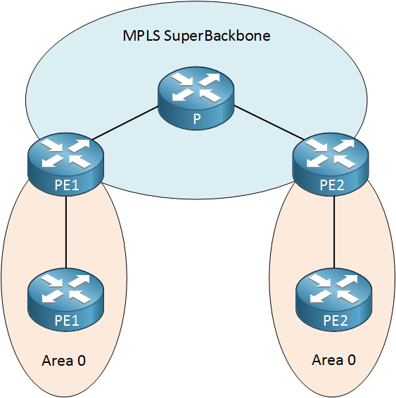
Both of our customer sites are using OSPF area 0, normally it’s impossible to have two backbone areas unless you connect them to each other with a virtual link. When we use MPLS L3 VPN, the service provider network is seen by OSPF as the superbackbone:
This allows us to use area 0 on multiple sites without using virtual links, the superbackbone connects everything together. If you look on the CE routers you can see that they see the PE routers as ABR routers:
CE1#show ip ospf database | begin Summary
  Summary Net Link States (Area 0)

Link ID         ADV Router      Age         Seq#       Checksum
5.5.5.5         192.168.12.2    1208        0x80000001 0x00C26C
192.168.45.0 192.168.12.2 1208 0x80000001 0x00FCB0CE2#show ip ospf database | begin Summary
Summary Net Link States (Area 0)
Link ID ADV Router Age Seq# Checksum
1.1.1.1 192.168.45.4 1223 0x80000001 0x008794
192.168.12.0 192.168.45.4 1223 0x80000001 0x007536
Above you can see that 192.168.12.2 (PE1) and 192.168.45.4 (PE2) are seen as ABR routers by the CE routers. The other question we still have to answer is how do the PE routers know to which area a prefix belongs and which LSA type to use when we redistribute a VPNv4 route back into OSPF for the customer?
Our PE routers need something to tell other PE routers which area and LSA type to use. We use two additional BGP extended communities for this:
- OSPF Domain Identifier: the domain ID is used to identify from what OSPF instance the route was redistributed.
- OSPF Route Type: the route type is used to identify what LSA we should use:
- Area number: the number of the area or 0 when it's an external route.
- Route Type: intra-area, inter-area, external, NSSA route.
Here's how you can see the OSPF domain identifier:
PE1#show ip ospf 2
 Routing Process "ospf 2" with ID 192.168.12.2
   Domain ID type 0x0005, value 0.0.0.2
 Start time: 6d05h, Time elapsed: 17:07:02.960
 Supports only single TOS(TOS0) routes
 Supports opaque LSA
 Supports Link-local Signaling (LLS)
 Supports area transit capability
 Supports NSSA (compatible with RFC 1587)
Connected to MPLS VPN Superbackbone, VRF CUSTOMERPE2#show ip ospf 2
Routing Process "ospf 2" with ID 192.168.45.4
Domain ID type 0x0005, value 0.0.0.2
Start time: 6d22h, Time elapsed: 00:00:20.812
Supports only single TOS(TOS0) routes
Supports opaque LSA
Supports Link-local Signaling (LLS)
Supports area transit capability
Supports NSSA (compatible with RFC 1587)
Connected to MPLS VPN Superbackbone, VRF CUSTOMER
Above you can see the OSPF process for the customer VRF. The domain ID type is 0x0005 which is a default value on Cisco devices. The value is 0.0.0.2 because Cisco IOS uses the OSPF process ID for this.
Now let's take a look at the VPNv4 routes that our PE routers have created:
PE1#show bgp vpnv4 unicast all 1.1.1.1/32
BGP routing table entry for 1:1:1.1.1.1/32, version 2
Paths: (1 available, best #1, table CUSTOMER)
  Advertised to update-groups:
     1
  Local
    192.168.12.1 from 0.0.0.0 (3.3.3.3)
      Origin incomplete, metric 2, localpref 100, weight 32768, valid, sourced, best
      Extended Community: RT:1:1 OSPF DOMAIN ID:0x0005:0x000000020200
        OSPF RT:0.0.0.0:2:0 OSPF ROUTER ID:192.168.12.2:0
mpls labels in/out 16/nolabelPE2#show bgp vpnv4 unicast all 5.5.5.5/32
BGP routing table entry for 1:1:5.5.5.5/32, version 14
Paths: (1 available, best #1, table CUSTOMER)
Advertised to update-groups:
1
Local
192.168.45.5 from 0.0.0.0 (192.168.34.4)
Origin incomplete, metric 2, localpref 100, weight 32768, valid, sourced, best
Extended Community: RT:1:1 OSPF DOMAIN ID:0x0005:0x000000020200
OSPF RT:0.0.0.0:2:0 OSPF ROUTER ID:192.168.45.4:0
mpls labels in/out 16/nolabel
Above you can see the OSPF domain ID which is exactly the same on both routers since I used the same OSPF process ID (2). The route type can be read like this:
- Area: 0.0.0.0
- LSA Type: 2
- Options: 0
Don't confuse the RT (route target) with the OSPF RT (route type). They use the same two letters which makes it easy to confuse the two...
When the PE router redistributes a VPNv4 route into OSPF, it will check the domain ID and route type.
When the domain ID is the same then a LSA type 1, 2 or 3 will be redistributed as a LSA type 3. LSA type 5 or 7 will always remain the same.
If the domain ID is different then LSA type 1, 2 or 3 will always be redistributed as external prefixes. Let'see if this is true...I can easily test this by changing the OSPF process ID on one of the PE routers since this will change the domain ID:
PE2(config)#no router ospf 2

PE2(config)#router ospf 22 vrf CUSTOMER
PE2(config-router)#network 192.168.45.0 0.0.0.255 area 0
PE2(config-router)#redistribute bgp 234 subnets

PE2(config)#router bgp 234
PE2(config-router)#address-family ipv4 vrf CUSTOMER
PE2(config-router-af)#redistribute ospf 22
By changing the OSPF process ID, we have a different domain ID on PE2. Here's the result:
CE1#show ip route ospf | include O E2
O E2     5.5.5.5 [110/2] via 192.168.12.2, 00:01:22, FastEthernet0/0
O E2 192.168.45.0/24 [110/1] via 192.168.12.2, 00:01:22, FastEthernet0/0CE2#show ip route ospf | include O E2
O E2 1.1.1.1 [110/2] via 192.168.45.4, 00:02:11, FastEthernet0/0
O E2 192.168.12.0/24 [110/1] via 192.168.45.4, 00:02:11, FastEthernet0/0
Instead of O IA entries you now see O E2 entries. You can see that the domain ID has changed below:
PE1#show bgp vpnv4 unicast all 5.5.5.5/32 | include DOMAIN
Extended Community: RT:1:1 OSPF DOMAIN ID:0x0005:0x000000160200PE2#show bgp vpnv4 unicast all 1.1.1.1/32 | include DOMAIN
Extended Community: RT:1:1 OSPF DOMAIN ID:0x0005:0x000000020200
That's it for now, that concludes our basis MPLS VPN L3 PE-CE OSPF configuration.
Conclusion
In this lesson you have seen how to configure OSPF as the PE-CE routing protocol over a MPLS L3 VPN network and how it deals with different LSA types. There is more to explain however...for example, if we have a backup link between the customer sites where we use OSPF then we might run into issues.
If we configure OSPF area 0 on the backup link then our CE routers will always prefer these intra-areaprefixes over the inter-area prefixes that our MPLS VPN network offers. There is a solution for this which is called the OSPF sham link, we'll cover this in another lesson.
Another issue with this scenario is loop prevention. Theoretically, OSPF routes could be redistributed from OSPF into BGP and back into OSPF. This is something I'll also demonstrate in another lesson.
- Configurations
- CE1
- PE2
- P
- PE2
- CE2
Want to take a look for yourself? Here you will find the configuration of each device.
If you have any questions, feel free to leave a comment.
No comments:
Post a Comment