Wednesday 31 August 2016

RIP Timers

Update: how often to send updates in seconds
Invalid: how many seconds, since seeing a valid update, to consider the route invalid, and placing the route into hold down
Hold Down: Once in hold down, how long (in seconds) to “not believe” any equal or less impressive (worse) route updates for routes that are in hold down
Flush: how many seconds, since the last valid update, until we throw that route in the trash (garbage collection for un-loved non-updated routes)

TCP State Machine

TCP STATE MACHINE:
==================

The Simplified TCP Finite State Machine
In the case of TCP, the finite state machine can be considered to describe the “life stages” of a connection. Each connection between one TCP device and another begins in a null state where there is no connection, and then proceeds through a series of states until a connection is established. It remains in that state until something occurs to cause the connection to be closed again, at which point it proceeds through another sequence of transitional states and returns to the closed state.
The full description of the states, events and transitions in a TCP connection is lengthy and complicated—not surprising, since that would cover much of the entire TCP standard. For our purposes, that level of detail would be a good cure for insomnia but not much else. However, a simplified look at the TCP FSM will help give us a nice overall feel for how TCP establishes connections and then functions when a connection has been created.
Table 151 briefly describes each of the TCP states in a TCP connection, and also describes the main events that occur in each state, and what actions and transitions occur as a result. For brevity, three abbreviations are used for three types of message that control transitions between states, which correspond to the TCP header flags that are set to indicate a message is serving that function. These are:
  • SYN: A synchronize message, used to initiate and establish a connection. It is so named since one of its functions is to synchronizes sequence numbers between devices.
  • FIN: A finish message, which is a TCP segment with the FIN bit set, indicating that a device wants to terminate the connection.
  • ACK: An acknowledgment, indicating receipt of a message such as a SYN or a FIN.
Again, I have not shown every possible transition, just the ones normally followed in the life of a connection. Error conditions also cause transitions but including these would move us well beyond a “simplified” state machine. The FSM is also illustrated in Figure 210, which you may find easier for seeing how state transitions occur.

Table 151: TCP Finite State Machine (FSM) States, Events and Transitions
State
State Description
Event and Transition
CLOSED
This is the default state that each connection starts in before the process of establishing it begins. The state is called “fictional” in the standard. The reason is that this state represents the situation where there is no connection between devices—it either hasn't been created yet, or has just been destroyed. If that makes sense. J
Passive Open: A server begins the process of connection setup by doing a passive open on a TCP port. At the same time, it sets up the data structure (transmission control block or TCB) needed to manage the connection. It then transitions to the LISTEN state.
Active Open, Send SYN: A client begins connection setup by sending aSYN message, and also sets up a TCB for this connection. It then transitions to the SYN-SENT state.
LISTEN
A device (normally a server) is waiting to receive a synchronize (SYN) message from a client. It has not yet sent its own SYN message.
Receive Client SYN, Send SYN+ACK: The server device receives a SYNfrom a client. It sends back a message that contains its own SYN and also acknowledges the one it received. The server moves to the SYN-RECEIVED state.
SYN-SENT
The device (normally a client) has sent a synchronize (SYN) message and is waiting for a matching SYN from the other device (usually a server).
Receive SYN, Send ACK: If the device that has sent its SYN message receives a SYN from the other device but not an ACK for its own SYN, it acknowledges the SYN it receives and then transitions to SYN-RECEIVEDto wait for the acknowledgment to its SYN.
Receive SYN+ACK, Send ACK: If the device that sent the SYN receives both an acknowledgment to its SYN and also a SYN from the other device, it acknowledges the SYN received and then moves straight to theESTABLISHED state.
SYN-RECEIVED
The device has both received a SYN (connection request) from its partner and sent its own SYN. It is now waiting for an ACK to its SYN to finish connection setup.
Receive ACK: When the device receives the ACK to the SYN it sent, it transitions to the ESTABLISHED state.
ESTABLISHED
The “steady state” of an open TCP connection. Data can be exchanged freely once both devices in the connection enter this state. This will continue until the connection is closed for one reason or another.
Close, Send FIN: A device can close the connection by sending a message with the FIN (finish) bit sent and transition to the FIN-WAIT-1state.
Receive FIN: A device may receive a FIN message from its connection partner asking that the connection be closed. It will acknowledge this message and transition to the CLOSE-WAIT state.
CLOSE-WAIT
The device has received a close request (FIN) from the other device. It must now wait for the application on the local device to acknowledge this request and generate a matching request.
Close, Send FIN: The application using TCP, having been informed the other process wants to shut down, sends a close request to the TCP layer on the machine upon which it is running. TCP then sends a FIN to the remote device that already asked to terminate the connection. This device now transitions to LAST-ACK.
LAST-ACK
A device that has already received a close request and acknowledged it, has sent its own FIN and is waiting for an ACK to this request.
Receive ACK for FIN: The device receives an acknowledgment for its close request. We have now sent our FIN and had it acknowledged, and received the other device's FIN and acknowledged it, so we go straight to the CLOSED state.
FIN-WAIT-1
A device in this state is waiting for an ACK for a FIN it has sent, or is waiting for a connection termination request from the other device.
Receive ACK for FIN: The device receives an acknowledgment for its close request. It transitions to the FIN-WAIT-2 state.
Receive FIN, Send ACK: The device does not receive an ACK for its ownFIN, but receives a FIN from the other device. It acknowledges it, and moves to the CLOSING state.
FIN-WAIT-2
A device in this state has received an ACK for its request to terminate the connection and is now waiting for a matching FIN from the other device.
Receive FIN, Send ACK: The device receives a FIN from the other device. It acknowledges it and moves to the TIME-WAIT state.
CLOSING
The device has received a FIN from the other device and sent an ACK for it, but not yet received an ACK for its own FIN message.
Receive ACK for FIN: The device receives an acknowledgment for its close request. It transitions to the TIME-WAIT state.
TIME-WAIT
The device has now received a FIN from the other device and acknowledged it, and sent its own FIN and received an ACK for it. We are done, except for waiting to ensure the ACK is received and prevent potential overlap with new connections. (See the topic describing connection termination for more details on this state.)
Timer Expiration: After a designated wait period, device transitions to theCLOSED state.


Figure 210: The TCP Finite State Machine (FSM)
This diagram illustrates the simplified TCP FSM.

Tuesday 30 August 2016

ICMP REDIRECT

Internet Control Message Protocol (ICMP) is used to communicate to the original source, the errors encountered while routing the packets, and exercise control on the traffic. This document discusses ICMP redirects and when redirects happen in a network.

Prerequisites

Requirements

Knowledge of IP protocol suite is necessary.

Components Used

This is supported in all series of Cisco routers and Cisco IOS® Software releases.

Conventions

For more information on document conventions, refer to the Cisco Technical Tips Conventions.

How ICMP Redirect Messages Work

ICMP redirect messages are used by routers to notify the hosts on the data link that a better route is available for a particular destination.
For example, the two routers R1 and R2 are connected to the same Ethernet segment as Host H. The default gateway for Host H is configured to use router R1. Host H sends a packet to router R1 to reach the destination on Remote Branch office Host 10.1.1.1. Router R1, after it consults its routing table, finds that the next-hop to reach Host 10.1.1.1 is router R2. Now router R1 must forward the packet out the same Ethernet interface on which it was received. Router R1 forwards the packet to router R2 and also sends an ICMP redirect message to Host H. This informs the host that the best route to reach Host 10.1.1.1 is by way of router R2. Host H then forwards all the subsequent packets destined for Host 10.1.1.1 to router R2.
43_01.gif
This debug message shows router R1, as in the network diagram, sending an ICMP redirect message to Host H (172.16.1.1).
R1#
debug ip icmp


ICMP packet debugging is on

*Mar 18 06:28:54: ICMP:redirect sent to 172.16.1.1 for dest 10.1.1.1, use gw 172.16.1.200

R1# 
Router R1 (172.16.1.100) sends a redirect to Host H (172.16.1.1) to use router R2 (172.16.1.200) as the gateway to reach the destination 10.1.1.1.

When Are ICMP Redirects Sent?

Cisco routers send ICMP redirects when all of these conditions are met:
  • The interface on which the packet comes into the router is the same interface on which the packet gets routed out.
  • The subnet or network of the source IP address is on the same subnet or network of the next-hop IP address of the routed packet.
  • The datagram is not source-routed.
  • The kernel is configured to send redirects. (By default, Cisco routers send ICMP redirects. The interface subcommand no ip redirects can be used to disable ICMP redirects.)
Note: ICMP redirects are disabled by default if Hot Standby Router Protocol (HSRP) is configured on the interface. In Cisco IOS Software Release 12.1(3)T and later, ICMP Redirect is allowed to be enabled on interfaces configured with HSRP. For more information, refer to HSRP Support for ICMP Redirects section of Hot Standby Router Protocol Features and Functionality.
For example, if a router has two IP addresses on one of its interfaces:
  interface ethernet 0

  ip address 171.68.179.1 255.255.255.0

  ip address 171.68.254.1 255.255.255.0 secondary
If the router receives a packet that is sourced from a host in the subnet 171.68.179.0 and destined to a host in the subnet 171.68.254.0, the router does not send an ICMP redirect because only the first condition is met, not the second.
The original packet for which the router sends a redirect still gets routed to the correct destinatio

Proxy ARP

we’ll use the following topology for this:
ARP Proxy ARP Example Topology
In the example above we have two subnets: 10.1.1.0 /24 and 10.2.2.0 /24. The router in the middle is connected to both subnets. On the bottom you see two hosts and on top we have a server.
When you take a close look at the hosts you can see that host A has a /24 subnet mask and host B has a /8 subnet mask. When host A tries to reach the server at 10.2.2.100 the following will happen:
  1. Host A compares its IP address and subnet mask to the IP address of the server (10.2.2.100) and decides that the server is in another subnet.
  2. Host A decides to send the packet for the server to its default gateway (10.1.1.254).
  3. Host A checks its ARP table to see if there is an entry for 10.1.1.254, if not it will send an ARP request.
  4. The router will respond to the ARP request, sending its MAC address of its FastEthernet 0/0 interface.
This is how ARP works normally, when host B tries to send an IP packet towards the server something else will happen:
  1. Host B compares its IP address and subnet mask to the IP address of the server (10.2.2.100) and decides that the server is in the same subnet.
  2. Host B checks its ARP table to see if there is an entry for 10.2.2.100, if not it will send an ARP request.
The server however is not on the 10.1.1.0 /24 subnet and routers do not forward broadcast traffic so the ARP request never makes it to the server. All hope is not lost however….this is where proxy ARP comes to the rescue!
When proxy ARP is enabled on the router, this is what happens:
  1. The router sees the ARP request from host B on the 10.1.1.0 /24 subnet and sees that this is an ARP request for something in the 10.2.2.0 /24 subnet.
  2. The router realizes that it knows how to reach the 10.2.2.0 /24 subnet and decides to respond to the ARP request in order to help host B.
  3. The router sends an ARP reply to host B with its MAC address on the FastEthernet 0/0 interface.
Are you following me so far? Let me show you what this looks like on a real router.

Configuration

I will use the following topology to demonstrate proxy ARP:
Proxy ARP Configuration Example
It’s the same as the picture as I just showed you but I am using the routers in my lab. By disabling “ip routing” I can turn the routers into ordinary host devices. Let’s start by disabling routing on R1, R2 and the server:
HostA, HostB & Server(config)#
no ip routing
Let’s configure the default gateway on those devices:
HostA & HostB(config)#
ip default-gateway 10.1.1.254
Server(config)#ip default-gateway 10.2.2.254
Let’s configure all the IP addresses that we require:
HostA(config)#interface fastEthernet 0/0
HostA(config-if)#ip address 10.1.1.1 255.255.255.0
HostB(config)#interface fastEthernet 0/0
HostB(config-if)#ip address 10.1.1.2 255.0.0.0
Server(config)#interface FastEthernet 0/0
Server(config-if)#ip address 10.2.2.100 255.255.255.0
Note that I used the /8 subnet mask on Host B here. Here’s the router:
R1(config)#interface FastEthernet 0/0
R1(config-if)#ip address 10.1.1.254 255.255.255.0
R1(config-if)#interface FastEthernet 0/1
R1(config-if)#ip address 10.2.2.254 255.255.255.0
That’s all we have to configure…let’s verify our work!

Gratuitous ARP

Gratuitous ARP is a special ARP (Address Resolution Protocol) reply that is not a response to an ARP request. A Gratuitous ARP reply is a reply to without a ARP request. No reply is expected for a Gratuitous ARP . A Gratuitous ARP packet has the following characteristics.
• The source and destination IP Addresses are both set to the IP of the machine sending the Gratuitous ARP packet.
• Destination MAC address is the broadcast MAC address ff:ff:ff:ff:ff:ff.
Gratuitous ARP packets are generated by network devices for some of the reasons listed below.
• To detect duplicate IPv4 addresses. When a reply to a gratuitous ARP request is received, computers can detect IPv4 address conflict in the network.
• To update ARP tables after a IPv4 address or MAC address change

Following Wireshark capture screenshot shows a Gratuitous ARP packet.
Gratuitus ARP

ARP

ARP REQUEST:
===========
Following screen shot shows the Wireshark capture window of ARP Request message. You must compare the below screen shot with ARP message format image at the beginning of this lesson. We can see from the below screen shot that the Destination MAC Address is FF:FF:FF:FF:FF:FF (Broadcast MAC Address), ARP opcode is 1 (for ARP Request), and the Target MAC Address is 00:00:00:00:00:00, which is unknown at this instance.
We can also see from the below screen shot that the Source IP Address is 192.168.0.84, Destination IP Address is 192.168.0.122, Source MAC Address 08:00:27:58:58:98 and Destination MAC Address is 00:00:00:00:00:00.
ARP Request Wireshark Capture

ARP REPLY:
===========
The "Sender MAC Address" field (which is marked below) in ARP Reply is the answer for ARP Request.
ARP Reply wireshark capture

Thursday 25 August 2016

BGP MESSAGE TYPES

BGP Messages

11 votes
BGP uses a variety of messages for establishing the connection, exchanging routing information, checking if the remote BGP neighbor is still there and/or notifying the remote side if any errors occur.
To do all of this, BGP uses 4 messages:
  • Open Message
  • Update Message
  • Keepalive Message
  • Notification Message
All of these BGP messages use a fixed-size header, it includes a type field that indicates what type of message it is.
To explain these BGP messages I will show you some Wireshark captures. I will use the following topology for this:
BGP R1 R2 AS1 AS2 Topology

Open Message

Once two BGP routers have completed a TCP 3-way handshake they will attempt to establish a BGP session, this is done using open messages. In the open message you will find some information about the BGP router, these have to be negotiated and accepted by both routers before we can exchange any routing information. Here are some of the items you will find in the open message:
  • Version: this includes the BGP version that the router is using. The current version of BGP is version 4 which is described in RFC 4271. Two BGP routers will try to negotiate a compatible version, when there is a mismatch then there will be no BGP session.
  • My AS: this includes the AS number of the BGP router, the routers will have to agree on the AS number(s) and it also defines if they will be running iBGP or eBGP.
  • Hold Time: if BGP doesn’t receive any keepalive or update messages from the other side for the duration of the hold time then it will declare the other side ‘dead’ and it will tear down the BGP session. By default the hold time is set to 180 seconds on Cisco IOS routers, the keepalive message is sent every 60 seconds. Both routers have to agree on the hold time or there won’t be a BGP session.
  • BGP Identifier: this is the local BGP router ID which is elected just like OSPF does:
    • Use the router-ID that was configured manually with the bgp router-id command.
    • Use the highest IP address on a loopback interface.
    • Use the highest IP address on a physical interface.
  • Optional Parameters: here you will find some optional capabilities of the BGP router. This field has been added so that new features could be added to BGP without having to create a new version.Things you might find here are:
Here’s an example of a wireshark capture of an open message between R1 and R2:
Wireshark Capture BGP Open Message
Above you can see the open message from R1 to R2. You can see the things that we discussed, the BGP version, AS number, hold time, BGP ID and the optional parameters (MP-BGP and route refresh). The marker field on top is used to indicate if we use MD5 authentication or not. When it’s filled with 1’s then we are not using authentication.

Update Message

Once two routers have become BGP neighbors, they can start exchanging routing information. This is done with the update message. In the update message you will find information about the prefixes that are advertised.In “BGP language” a prefix is referred to as NLRI (Network Layer Reachability Information). Here are some of the things you will find in an update message:
  • Withdrawn Route Length: this field shows the length of the Withdrawn Routes field in bytes. When it is set to 0, there are no routes withdrawn and the Withdrawn Routes field will not show up.
  • Withdrawn Routes: this field shows all the prefixes that should be removed from the BGP table.
  • Total Path Attribute Length: here you will find the total length of the Path Attributes field.
  • Path Attributes: the BGP attributes for the prefix are stored here, for example: origin, as_path, next_hop, med, local preference, etc. These path attributes are stored in TLV-format (Type, Length, Value).
Each of the BGP attributes also has an attribute flag that tells the BGP router how to treat the attribute. Here are the different bit flags:
  • Optional: when the attribute is well-known this bit is set to 0, when its optional it is set to 1.
  • Transitive: when an optional attribute is non-transitive this bit is set to 0, when it is transitive it is set to 1.
  • Partial: when an optional attribute is complete this bit is set to 0, when it’s partial it is set to 1.
  • Extended Length: when the attribute length is 1 octet it is set to 0, for 2 octets it is set to 1. This extended length flag may only be used if the length of the attribute value is greater than 255 octets.
Let’s take a look at an update message from R1:
R1(config)#router bgp 1
R1(config-router)#network 1.1.1.1 mask 255.255.255.255
Here’s the capture:
Wireshark Capture BGP Update Route Message
Above you can see a update message from R1. No routes are withdrawn and there are a couple of BGP attributes. You can see the ORIGIN, AS_PATH and MULTI_EXIT_DISC (MED). I also highlighted some of the flags. The AS_PATH attribute is transitive while MULTI_EXIT_DISC is optional. At the bottom you can find the NLRI information with our prefix.
Let’s remove the network command for the loopback interface on R1 so that we can see a withdrawn in the update message:
R1(config)#interface loopback 0
R1(config-if)#shutdown
Here’s the capture:
Wireshark Capture BGP Update Withdrawn Message
Here you can see the withdrawn routes length which is 5 bytes. In the Withdrawn Routes field we see our 1.1.1.1 /32 prefix that should be removed.

Keepalive Message

When there are no routes to be advertised or withdrawn, there's not much our BGP neighbors have to share with each other. To make sure the other side is "still there" we use these periodic keepalive messages. By default, BGP sends 19 byte long keepalive messages every 60 seconds. When a remote BGP neighbor misses three keepalives (3 x 60 = 180 seconds, the value of the hold time) it will flush the routes from the BGP neighbor.
Here's a capture of a keepalive message:
Wireshark Capture BGP Keepalive Message
The keepalive message is really simple, it's just a basic header with the length (19 bytes) and the type.

Notification Message

The notification message is used when an error occurs which will result in termination of the BGP neighbor adjacency. When something goes wrong, the notification message will be sent and the session will be terminated.
The TCP session will be cleared, all entries from this BGP neighbor will be removed from the BGP table and update messages with route withdrawals will be sent to other BGP neighbors.
There is a list with BGP error codes and each error code has a sub-type. Here are some examples:
  • Message header error
  • Open message error
  • Update message error
For each of those there is a subtype that explains the exact error. For example for the open message here are some of the subtypes:
  • Unsupported version number
  • Bad peer AS
  • Bad BGP identifier
  • Unsupported optional parameter
  • Unacceptable hold time
The list with all error codes and their subtypes is quite large. If you want to see all of them, take a look at this list from IANA.
Let me show you an example of a notification message, we'll do something that BGP doesn't like:
R2(config)#no router bgp 2
R2(config)#router bgp 22
R2(config-router)#neighbor 192.168.12.1 remote-as 1
By changing the AS number on one of the routers we will have a mismatch. Here's the wireshark capture:
Wireshark capture BGP notification message
R1 is sending R2 a notification message with a major error "open message error" and the minor error code (subtype) is bad peer AS.

Any Transport Over MPLS(AToM)

Any Transport over MPLS (AToM) will transport layer 2 frames over a MPLS (Multiprotocol Label Switching) network. This will allow service providers to connect layer 2 networks of customers transparently by using their MPLS backbone. AToM can transport the following:
  • ATM AAL5
  • ATM Cell Relay
  • Ethernet
  • Frame Relay
  • PPP
  • HDLC
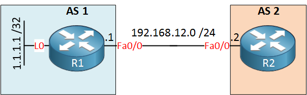
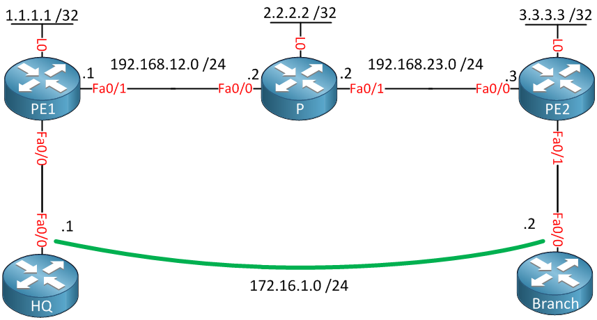
I will give you an example how to configure AToM to transport Ethernet over the MPLS backbone, we will use the following topology to do this:
MPLS Atom Ethernet
Above you see a small MPLS backbone that consists of the PE1, P and PE2 router. This ISP only has one customer that has a HQ and Branch. The customer wants to have the HQ and Branch router to be in the same layer 2 segment.

Configuration

First we will enable OSPF to advertise the loopback interfaces, these will be used as the router ID for MPLS LDP:
PE1(config)#router ospf 1
PE1(config-router)#network 192.168.12.0 0.0.0.255 area 0
PE1(config-router)#network 1.1.1.1 0.0.0.0 area 0
P(config)#router ospf 1
P(config-router)#network 192.168.12.0 0.0.0.255 area 0
P(config-router)#network 192.168.23.0 0.0.0.255 area 0
P(config-router)#network 2.2.2.2 0.0.0.0 area 0
PE2(config)#router ospf 1
PE2(config-router)#network 192.168.23.0 0.0.0.255 area 0
PE2(config-router)#network 3.3.3.3 0.0.0.0 area 0
Now we will enable MPLS LDP on the interfaces connecting the PE1, P and PE2 routers:
PE1(config)#interface fastEthernet 0/1
PE1(config-if)#mpls ip
P(config)#interface fastEthernet 0/0
P(config-if)#mpls ip

P(config)#interface fastEthernet 0/1
P(config-if)#mpls ip 
PE2(config)#interface fastEthernet 0/0
PE2(config-if)#mpls ip
Just to be sure let’s verify that we have LDP neighbors:
P#show mpls ldp neighbor | include Peer
    Peer LDP Ident: 1.1.1.1:0; Local LDP Ident 2.2.2.2:0
    Peer LDP Ident: 3.3.3.3:0; Local LDP Ident 2.2.2.2:0
That seems to be the case! Now we can configure AToM so that the HQ and Branch router are able to reach each other:
PE1(config)#interface fastEthernet 0/0
PE1(config-if)#xconnect 3.3.3.3 13 encapsulation mpls
PE2(config)#interface fastEthernet 0/1
PE2(config-if)#xconnect 1.1.1.1 13 encapsulation mpls
We need to use the xconnect command between PE1 and PE2. The VC ID (13) has to be the same on both routers.

Verification

First we will check our LDP peers:
PE1#show mpls ldp neighbor 3.3.3.3
    Peer LDP Ident: 3.3.3.3:0; Local LDP Ident 1.1.1.1:0
 TCP connection: 3.3.3.3.64567 - 1.1.1.1.646
 State: Oper; Msgs sent/rcvd: 15/15; Downstream
 Up time: 00:05:19
 LDP discovery sources:
   Targeted Hello 1.1.1.1 -> 3.3.3.3, active, passive
        Addresses bound to peer LDP Ident:
          192.168.23.3    3.3.3.3 
PE2#show mpls ldp neighbor 1.1.1.1
    Peer LDP Ident: 1.1.1.1:0; Local LDP Ident 3.3.3.3:0
 TCP connection: 1.1.1.1.646 - 3.3.3.3.64567
 State: Oper; Msgs sent/rcvd: 15/15; Downstream
 Up time: 00:05:38
 LDP discovery sources:
   Targeted Hello 3.3.3.3 -> 1.1.1.1, active, passive
        Addresses bound to peer LDP Ident:
          192.168.12.1    1.1.1.1 
PE1 and PE2 are LDP neighbors, now we'll verify that they are transporting our Ethernet traffic:
PE1#show mpls l2transport binding 
  Destination Address: 3.3.3.3,  VC ID: 13
    Local Label:  19
        Cbit: 1,    VC Type: Ethernet,    GroupID: 0
        MTU: 1500,   Interface Desc: n/a
        VCCV: CC Type: CW [1], RA [2]
              CV Type: LSPV [2]
    Remote Label: 19
        Cbit: 1,    VC Type: Ethernet,    GroupID: 0
        MTU: 1500,   Interface Desc: n/a
        VCCV: CC Type: CW [1], RA [2]
              CV Type: LSPV [2]
PE2#show mpls l2transport binding 
  Destination Address: 1.1.1.1,  VC ID: 13
    Local Label:  19
        Cbit: 1,    VC Type: Ethernet,    GroupID: 0
        MTU: 1500,   Interface Desc: n/a
        VCCV: CC Type: CW [1], RA [2]
              CV Type: LSPV [2]
    Remote Label: 19
        Cbit: 1,    VC Type: Ethernet,    GroupID: 0
        MTU: 1500,   Interface Desc: n/a
        VCCV: CC Type: CW [1], RA [2]
              CV Type: LSPV [2]
A label has been assigned to this virtual circuit, you can see it says "Ethernet". There's another useful command that lets us check the AToM configuration:
PE1#show mpls l2transport vc 

Local intf     Local circuit              Dest address    VC ID      Status    
-------------  -------------------------- --------------- ---------- ----------
Fa0/0          Ethernet                   3.3.3.3         13         UP
PE2#show mpls l2transport vc

Local intf     Local circuit              Dest address    VC ID      Status    
-------------  -------------------------- --------------- ---------- ----------
Fa0/1          Ethernet                   1.1.1.1         13         UP 
Above you have a nice overview with the interfaces, transport type, virtual circuit ID and the status. Everything is looking good to let's give it a test drive:
HQ#ping 172.16.1.2

Type escape sequence to abort.
Sending 5, 100-byte ICMP Echos to 172.16.1.2, timeout is 2 seconds:
!!!!!
Success rate is 100 percent (5/5), round-trip min/avg/max = 16/20/40 ms
Our ping is successful, we can verify the number of packets that have been sent as following:
PE1#show mpls l2transport vc detail            
Local interface: Fa0/0 up, line protocol up, Ethernet up
  Destination address: 3.3.3.3, VC ID: 13, VC status: up
    Next hop: 192.168.12.2
    Output interface: Fa0/1, imposed label stack {17 19}
  Create time: 00:09:46, last status change time: 00:09:41
  Signaling protocol: LDP, peer 3.3.3.3:0 up
    MPLS VC labels: local 19, remote 19 
    Group ID: local 0, remote 0
    MTU: local 1500, remote 1500
    Remote interface description: 
  Sequencing: receive disabled, send disabled
  VC statistics:
    packet totals: receive 84, send 83
    byte totals:   receive 9445, send 9045
    packet drops:  receive 0, seq error 0, send 0
That's how you configure AToM to transport Ethernet. I hope this has been useful to you, if you enjoyed this lesson please share it with your friends.