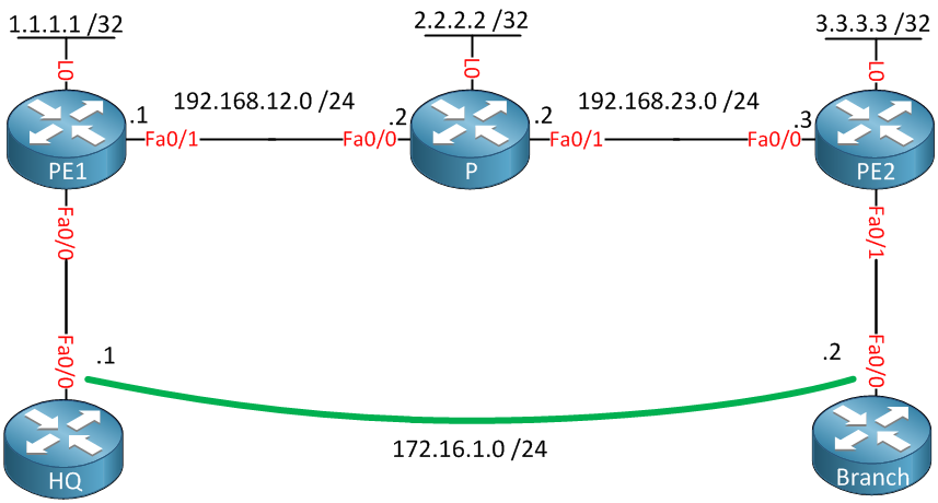
Any Transport over MPLS (AToM) will transport layer 2 frames over a MPLS (Multiprotocol Label Switching) network. This will allow service providers to connect layer 2 networks of customers transparently by using their MPLS backbone. AToM can transport the following:
- ATM AAL5
- ATM Cell Relay
- Ethernet
- Frame Relay
- PPP
- HDLC
I will give you an example how to configure AToM to transport Ethernet over the MPLS backbone, we will use the following topology to do this:

Above you see a small MPLS backbone that consists of the PE1, P and PE2 router. This ISP only has one customer that has a HQ and Branch. The customer wants to have the HQ and Branch router to be in the same layer 2 segment.
Configuration
First we will enable OSPF to advertise the loopback interfaces, these will be used as the router ID for MPLS LDP:
PE1(config)#router ospf 1
PE1(config-router)#network 192.168.12.0 0.0.0.255 area 0
PE1(config-router)#network 1.1.1.1 0.0.0.0 area 0P(config)#router ospf 1
P(config-router)#network 192.168.12.0 0.0.0.255 area 0
P(config-router)#network 192.168.23.0 0.0.0.255 area 0
P(config-router)#network 2.2.2.2 0.0.0.0 area 0PE2(config)#router ospf 1
PE2(config-router)#network 192.168.23.0 0.0.0.255 area 0
PE2(config-router)#network 3.3.3.3 0.0.0.0 area 0
Now we will enable MPLS LDP on the interfaces connecting the PE1, P and PE2 routers:
PE1(config)#interface fastEthernet 0/1
PE1(config-if)#mpls ipP(config)#interface fastEthernet 0/0
P(config-if)#mpls ip
P(config)#interface fastEthernet 0/1
P(config-if)#mpls ip PE2(config)#interface fastEthernet 0/0
PE2(config-if)#mpls ip
Just to be sure let’s verify that we have LDP neighbors:
P#show mpls ldp neighbor | include Peer
    Peer LDP Ident: 1.1.1.1:0; Local LDP Ident 2.2.2.2:0
    Peer LDP Ident: 3.3.3.3:0; Local LDP Ident 2.2.2.2:0
That seems to be the case! Now we can configure AToM so that the HQ and Branch router are able to reach each other:
PE1(config)#interface fastEthernet 0/0
PE1(config-if)#xconnect 3.3.3.3 13 encapsulation mplsPE2(config)#interface fastEthernet 0/1
PE2(config-if)#xconnect 1.1.1.1 13 encapsulation mpls
We need to use the xconnect command between PE1 and PE2. The VC ID (13) has to be the same on both routers.
Verification
First we will check our LDP peers:
PE1#show mpls ldp neighbor 3.3.3.3
    Peer LDP Ident: 3.3.3.3:0; Local LDP Ident 1.1.1.1:0
 TCP connection: 3.3.3.3.64567 - 1.1.1.1.646
 State: Oper; Msgs sent/rcvd: 15/15; Downstream
 Up time: 00:05:19
 LDP discovery sources:
   Targeted Hello 1.1.1.1 -> 3.3.3.3, active, passive
        Addresses bound to peer LDP Ident:
192.168.23.3 3.3.3.3 PE2#show mpls ldp neighbor 1.1.1.1
Peer LDP Ident: 1.1.1.1:0; Local LDP Ident 3.3.3.3:0
TCP connection: 1.1.1.1.646 - 3.3.3.3.64567
State: Oper; Msgs sent/rcvd: 15/15; Downstream
Up time: 00:05:38
LDP discovery sources:
Targeted Hello 3.3.3.3 -> 1.1.1.1, active, passive
Addresses bound to peer LDP Ident:
192.168.12.1 1.1.1.1
PE1 and PE2 are LDP neighbors, now we'll verify that they are transporting our Ethernet traffic:
PE1#show mpls l2transport binding
  Destination Address: 3.3.3.3,  VC ID: 13
    Local Label:  19
        Cbit: 1,    VC Type: Ethernet,    GroupID: 0
        MTU: 1500,   Interface Desc: n/a
        VCCV: CC Type: CW [1], RA [2]
              CV Type: LSPV [2]
    Remote Label: 19
        Cbit: 1,    VC Type: Ethernet,    GroupID: 0
        MTU: 1500,   Interface Desc: n/a
        VCCV: CC Type: CW [1], RA [2]
CV Type: LSPV [2]PE2#show mpls l2transport binding
Destination Address: 1.1.1.1, VC ID: 13
Local Label: 19
Cbit: 1, VC Type: Ethernet, GroupID: 0
MTU: 1500, Interface Desc: n/a
VCCV: CC Type: CW [1], RA [2]
CV Type: LSPV [2]
Remote Label: 19
Cbit: 1, VC Type: Ethernet, GroupID: 0
MTU: 1500, Interface Desc: n/a
VCCV: CC Type: CW [1], RA [2]
CV Type: LSPV [2]
A label has been assigned to this virtual circuit, you can see it says "Ethernet". There's another useful command that lets us check the AToM configuration:
PE1#show mpls l2transport vc

Local intf     Local circuit              Dest address    VC ID      Status
-------------  -------------------------- --------------- ---------- ----------
Fa0/0          Ethernet                   3.3.3.3         13         UP
PE2#show mpls l2transport vc
Local intf Local circuit Dest address VC ID Status
------------- -------------------------- --------------- ---------- ----------
Fa0/1 Ethernet 1.1.1.1 13 UP
Above you have a nice overview with the interfaces, transport type, virtual circuit ID and the status. Everything is looking good to let's give it a test drive:
HQ#ping 172.16.1.2

Type escape sequence to abort.
Sending 5, 100-byte ICMP Echos to 172.16.1.2, timeout is 2 seconds:
!!!!!
Success rate is 100 percent (5/5), round-trip min/avg/max = 16/20/40 ms
Our ping is successful, we can verify the number of packets that have been sent as following:
PE1#show mpls l2transport vc detail
Local interface: Fa0/0 up, line protocol up, Ethernet up
  Destination address: 3.3.3.3, VC ID: 13, VC status: up
    Next hop: 192.168.12.2
    Output interface: Fa0/1, imposed label stack {17 19}
  Create time: 00:09:46, last status change time: 00:09:41
  Signaling protocol: LDP, peer 3.3.3.3:0 up
    MPLS VC labels: local 19, remote 19
    Group ID: local 0, remote 0
    MTU: local 1500, remote 1500
    Remote interface description:
  Sequencing: receive disabled, send disabled
  VC statistics:
    packet totals: receive 84, send 83
    byte totals:   receive 9445, send 9045
    packet drops:  receive 0, seq error 0, send 0
That's how you configure AToM to transport Ethernet. I hope this has been useful to you, if you enjoyed this lesson please share it with your friends.
No comments:
Post a Comment